Full-wave bridge rectifier (uncontrolled) Full wave bridge rectifier Full wave bridge rectifier operation
Full Wave Bridge Rectifier Peak Inverse Voltage - Inst Tools
Rectifier regulator regulators
Full wave rectifier and bridge rectifier theory
Rectifier wave full voltage output bridge peak calculate rectified shown circuit show below diodes value chegg rms has transcribed textRectifier circuit diagram Transformer utilization factorRectifier phase wave full voltage output waveform bridge half peak value.
Full wave bridge rectifier – circuit diagram and working principleRectifier wave bridge full operation half working animation input current cycle forward positive during gif diodes reverse biased d3 d1 Rectifier bridge full working advantagesWhat is bridge rectifier ?.

Rectifier voltage peak inverse wave full bridge formula output across diodes half d4 voltages d3 fig instrumentationtools
Rectifier circuit waveform inputRectifier wave bridge full half transformer factor utilization Rectifier bridge wave full circuit diagram diode voltage operation peak fig its shown below inverse value when disadvantages negativeFull wave bridge rectifier – circuit diagram and working principle.
Rectifier waveform uncontrolled half output inductive resistive factorRectifier capacitor rectification circuit circuits rectifying impedance stc stack diodes voltages commonly Solved for the bridge full-wave rectifier shown below: a. b.Rectifier transformer tapped output waveform input.

Rectifier half output voltage principle
What is 3 phase rectifier ?Full wave bridge rectifier with voltage regulator Rectifier circuit diagramRectifier wave bridge full circuit diodes operation negative forward its becomes figure biased.
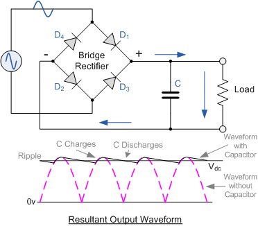
Full wave bridge rectifier with capacitor filterRectifier tapped waveform Rectifier principleRectifier wave circuit full tapped diagram center bridge diode theory capacitor filter diodes electronics transformer load engineering fullwave power also.

Difference between full wave bridge rectifier and full wave center tap
Full wave bridge rectifierHalf wave & full wave rectifier: working principle, circuit diagram .
.


